STM32 & OpenCM3 4: Memories and Latency
Mon, Jun 24, 2019This is the fifth post in a series on the STM32 series of MCUs. The previous post, on CANbus, can be found here.
As core frequencies increase, the performance penalty of loading instructions and data from slow flash memories increase. For a modern core such as the STM32F750 running at 216MHz, a single flash read can stall the CPU for 8 cycles. Luckily, on these faster cores exist mechanisms to ameliorate or eliminate these stalls. Here I will go over two methods: loading functions into SRAM for zero-wait-state execution, and enabling of the built-in I-cache on certain Cortex-M processors.
Executing from SRAM
Above a certain core frequency, it is no longer possible for the attached flash memory to keep up. This results in the need for ‘wait states’ inside the CPU - in order to progress to the next instruction, the CPU must stall and wait for the fetch from flash to complete. Even worse, the faster your CPU frequency gets, the more pronounced this problem becomes.
A first solution to this, that works on all embedded microcontrollers which allow executing from memory, is to simply copy the code to be executed from flash into SRAM once at startup, and then run it from there afterwards. Since most microcontrollers have single-cycle access latency for SRAM, this can increase execution time significantly. Even on microcontrollers that support some amount of prefetching, copying functions to memory can be useful for code that must execute in deterministic time, or that is frequently jumped to from unpredictable locations (for example, interrupt service routines).
Luckily, there is a way to achieve this with GNU utilities. By
default, all code will be placed into the .text section by your compiler.
But it doesn’t have to! We can create our own sections, and do as we please
with them. So for now, let’s create a section called sram_func and designate
a function as being part of this section. First, let’s edit our linker script
to tell it where the new section should go, and what it should contain.
/* Presumably, you already have a section like this defining the physical layout
   of your particular microcontroller */
MEMORY
{
    rom (rx) : ORIGIN = 0x08000000, LENGTH = 64K
    ram (rwx) : ORIGIN = 0x20000000, LENGTH = 320K
}

/* Other existing directives should likely be kept above this new section,
   unless you already have something fancy going on and know better */

/* Now, we can create a new section definition */
SECTIONS {
.sram_func : { /* Our new section will be called .sram_func */
    /* This creates a new variable, accessible from our C code, which points
       to the start address of our newly created section, in memory.
       The reason for this will become apparent later. */
    __sram_func_start = .;
    /* We now tell the linker that into the .sram_func section it should place
       all of the section data we will later tag as 'sram_func'. */
    *(sram_func)
    /* Pad the end of our section if necessary to ensure that it is aligned on a
       32-bit word boundary */
    . = ALIGN(4);
    /* We now take the end address of this new section, and make it also
       available to the program. */
    __sram_func_end = .;
} >ram AT>rom /* These two directives control the LMA and VMA for this section:
                 we state that it should be stored in rom (so that it can
                 actually be programmed onto your microcontroller), but
                 referenced at a location inside our ram segment. */
/* For our final directive, we need to know the location in ROM to load
   the data _from_ at the start of execution. */
__sram_func_loadaddr = LOADADDR(.sram_func);
}
Now that we have a place to put these functions, we can tell GCC to place them
there using a small __attribute__ directive:
__attribute__((section("sram_func")))
void exti1_isr(void) {
    // Body of a time-sensitive interrupt goes here
    gpio_set(GPIOA, GPIO1);
    // [...]
    gpio_clear(GPIOA, GPIO1);
}
With the addition of our __attribute__ field, gcc now knows to keep our
function in a new section, and we can verify this with objdump:
$ arm-none-eabi-nm -f sysv -C my_elf_file
Name                  Value   Class        Type         Size     Line  Section
[...]
exti0_isr           |080017fc|   W  |              FUNC|00000014|     |.text
exti1_isr           |20000330|   T  |              FUNC|00000028|     |.sram_func
exti2_isr           |080017fc|   W  |              FUNC|00000014|     |.text
[...]
As you can see, the ISR we just tagged as being destined for sram_func is
no longer in the .text section, and the location of the symbol is not in the
0x0800 0000 ROM section, but the 0x2000 0000 SRAM area. So far so good, but
if we were to deploy this code to the device now, as soon as we actually
triggered the ISR we would almost certainly encounter a segmentation fault.
This is because we’ve told the linker that this code is located in RAM, but
haven’t actually set up a method to actually move that code into RAM - when
the microcontroller resets, that memory space will be initialized to junk.
In order to fix this, we need to add some code at the very start of our
application to actually read the data for the sram_func section out of ROM
and copy it into RAM, where it can then be called. To do so, we use the three
variables we defined earlier as part of the linker script:
// The variables defined in our linker script are available to us as externed
// unsigned words, the locations of which denote our sections.
extern unsigned __sram_func_start, __sram_func_end, __sram_func_loadaddr;
// Our sram_func_start and sram_func_end variables are located at the start and
// end of the memory space that we want to copy data into.
// The loadaddr variable is located in ROM, at the start of where the data to
// be copied is stored.
// Using these three variables, we can quickly copy the code across.
volatile unsigned *src = &__sram_func_loadaddr;
volatile unsigned *dest = &__sram_func_start;
while (dest < &__sram_func_end) {
*dest = *src;
src++;
dest++;
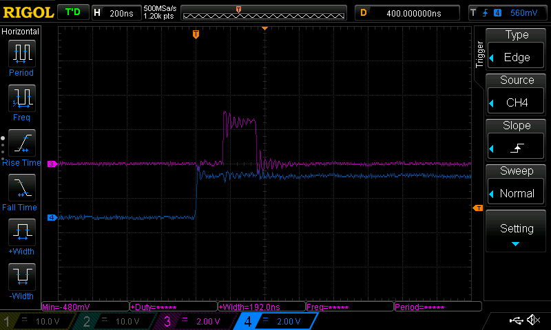
}Now that we’ve done that, let’s verify that this is indeed faster. As a testbed, I have a STM32F7 series MCU running at 216MHz. I have configured an EXTI interrupt that is triggered on rising edges, and when fired sets and clears a GPIO. The pin driving the EXTI interrupt is then connected to a function generator running at 1Hz, and the input function and GPIO pin are connected to a scope. Here is a representative trigger of the ISR running from flash memory, where the blue trace is the input signal, and the purple trace is the pin toggled by the ISR:
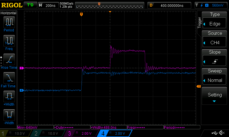
Interrupt latency running from flash
We can see that after the trigger pin goes high, we have a delay of almost exactly 400ns before the ISR triggers and pulls the GPIO pin high. At 216MHz, that’s close to 100 clock cycles! This is rather poor overhead, and for applications that make extensive use of interrupts, the delays will add up. Now let’s see what happens when we instead run our ISR out of SRAM:
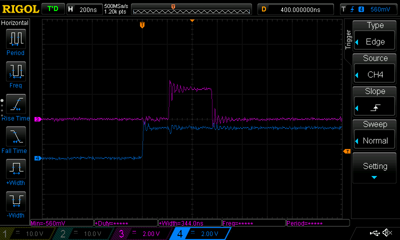
Interrupt latency running from SRAM
Not bad! The latency between the trigger going high and the GPIO going high has been cut in half, and the total execution time of the ISR has also dropped by a little under 200ns itself.
ITCM RAM
While loading code into memory can be useful for performance, it comes at the
obvious tradeoff of taking up additional space. Luckily, on some ARM platforms
exists a section of memory called ITCM, or the Instruction Tightly Coupled
Memory. Unlike its sister memory, the DTCM, the ITCM block can only be
accessed by the CPU, and not at all by peripherals such as DMA controllers. It
is also not located in a contiguous memory space with the rest of the system
memories: at least on the STM32F750, it is located at address 0x0000 0000,
unlike the rest of the volatile memories located at 0x2000 0000. Since it’s
so isolated, if you have it it is an excellent location for any functions you
may want to load into RAM.
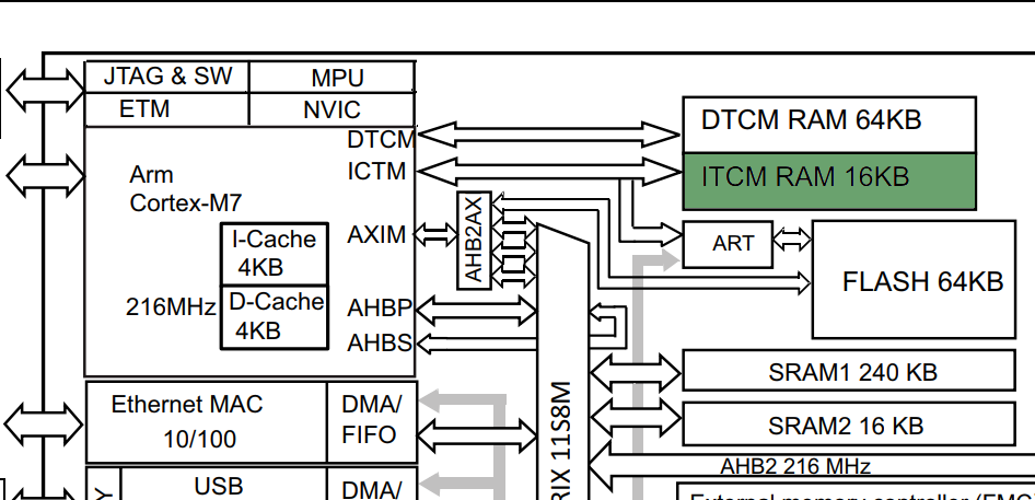
Block diagram of STM32F750 with ITCM highlighted
To use the ITCM as a space for functions that need to be able to execute quickly, we can edit our linker script from above with two small changes:
MEMORY {
    rom (rx) : ORIGIN = 0x08000000, LENGTH = 64K
    ram (rwx) : ORIGIN = 0x20000000, LENGTH = 320K
    /* Here we add a new memory region: the ITCM RAM */
    itcm (rwx) : ORIGIN = 0x00000000, LENGTH = 16K
}

SECTIONS {
.sram_func : {
    __sram_func_start = .;
    *(sram_func)
    . = ALIGN(4);
    __sram_func_end = .;
} >itcm AT>rom /* Instead of ram, we load to itcm */
__sram_func_loadaddr = LOADADDR(.sram_func);
}
No changes need to be made to our code that loads the function data from ROM, since after a recompilation the variables we used will automatically point at the new data location. Any functions loaded into memory in this block will not count against the memory space available to the program for heap, stack and globals.
I-Cache
Eagle-eyed readers may also notice another memory hidden away in the block diagram above:
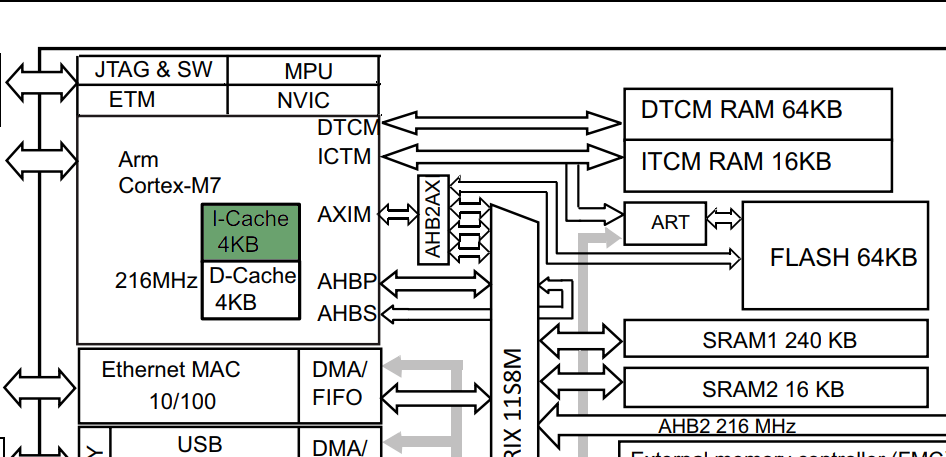
Block diagram of STM32F750 with I-Cache highlighted
Regardless of whether you use the manual memory loading above (which I would recommend for methods you need to guarantee run without wait states), you can gain an often significant general performance enhancement simply by enabling the L1 I-cache built directly into the ARM core (on models that have it, that is. Consult your data sheet!)
Unlike the ITCM RAM, the cache does not require manual management other than being turned on. To do so, we can follow the instructions from the ARM V7-M Architecture Reference Manual in section B2.2, “Caches and branch predictors”. As the document states, all caches are disabled at startup. To enable the I-cache, we need to first invalidate it, and then set a bit in the Cache Control Register to enable it. We only need two registers for this, so the code is relatively straightforward:
// Writing to the ICIALLU completely invalidates the entire instruction cache
#define ICIALLU (*(volatile uint32_t *)(0xE000EF50))
// The Configuration and Control Register contains the control bits for
// enabling/disabling caches
#define ARM_CCR (*(volatile uint32_t *)(0xE000ED14))

// We will also define two macros for data and instruction barriers
define __dsb asm __volatile__("dsb" ::: "memory")
define __isb asm __volatile__("isb" ::: "memory")

// Synchronize
__dsb; __isb;
// Invalidate the instruction cache
ICIALLU = 0UL;
// Re-synchronize
__dsb; __isb;
// Enable the I-cache
SCB->CCR |= (1 << 17);
// Force a final resync and clear of the instruction pipeline
__dsb; __isb;
You’ll note the inclusion of several dsb and isb blocks -
since we’re messing with instruction caches, it’s a good idea to add
some explicit synchronization barriers to the code. We will use DSB to prevent
execution from continuing before all in-flight memory accesses are complete.
We will also use ISB to flush the processor pipeline, forcing all following
instructions to be re-fetched.
Note that our inline assembly also specifies
the ‘memory’ clobber
flag since it
may change the global state, and so should not be reordered away by the
compiler.
When this cache is enabled, common codepaths will start to benefit passively. Even our already-optimized ISR will gain a little more performance from I-caching of GPIO manipulation code called from the ISR that wasn’t itself loaded into ITCM ram:
Interrupt latency running from RAM with I-Cache enabled
With these two tricks, you can unlock a significant amount of extra performance from your embedded system, and can even go further by enabling the D-cache also present in higher-spec ARM cores. However, be advised that with the D-cache comes pitfalls when it comes to non-TCM memories and DMA transfers.